


Surface coatings to increase the tool wear life
Producing
intricate shapes quickly with excellent precision and good surface quality at a
low cost is one of the advantages of die casting. But, maintaining this
advantage is difficult. A die casting die can cost more than the machine that
operates the die. Die casting is hard on dies and die components and pulling
the dies and pins for repair and/or to polish them is costly.

To help maintain the advantages of die casting and production up time, die life needs to be extended by reducing repairs. A tool treatment process called thermal diffusion (TD) can help die casters reduce maintenance and repairs and extend core and core pin life.
The
TD process prolongs die life by decreasing the damage caused by thermal and
mechanical cyclic loadings and the reaction with active cast materials that
severely damage dies and die components. It reduces the soldering, corrosion,
erosion, wash-out, wear and heat checking from the loadings and reactions with
other materials. It also provides excellent peel and adhesion strength. Die
life is significantly extended and repairs and polishing are reduced.
The
process also helps protect aluminum die casting dies which are especially
vulnerable to die casting problems.
One
of the reasons it works effectively in die cast operations is found in the
process itself. During the treatment process, the substrate surface of the core
and core pins is modified, creating a metallurgically bonded non-porous
vanadium carbide (VC) layer.
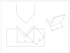
The
VC layer is infused into and onto the dies and die components (Fig. 1 & 2).
This VC layer is .0001- to .0006-inch thick and has a hardness of 3200 Vickers
at room temperature.
Even
under the high working temperatures used in die casting, the VC layer retains
its hardness level. And, once the die is cooled to room temperature, the original
hardness of VC is restored to previous levels.
For
example, at 800° Centigrade, the hardness of the VC layer drops to
approximately 900 Vickers, which is still above the hardness of other treated
surfaces. As the VC layer cools to room temperature, it returns to near its
original hardness of 3200 Vickers. Its ability to maintain its hardness under
high temperature applications allows it to perform well in casting operations.
The
process also is effective in die cast operations because the hardness of the VC
layer is higher than abrasives such as aluminum oxide, which is found in hone
stones and sandpaper used for polishing cores and pins. This allows any
aluminum that mechanically sticks to a pin to be easily removed without
significant damage or dimensional change to the pin. Polishing time and the
resultant wear on the pin are greatly reduced.
What is TD?
Developed
in Japan in 1969 at the Toyota Central Research and Development Laboratories,
Inc. by Dr. Tohru Arai, the TD process is a high-temperature tool treatment.
During the process a nonporous metallurgically bonded vanadium carbide (VC)
layer is diffused into and onto tooling substrate. The VC layer is .0001- to
.0006-inch thick and has a hardness of 3,200 to 3,800 on the Vickers hardness
scale. The VC layer retains its hardness under high temperature working
conditions like die casting.
Because
the VC layer is diffused into and onto the tool substrate, it significantly
reduces wear, soldering and corrosion and provides superior peel strength and
adhesion strength. It extends the life and performance of core pins, dies,
punches and tooling by 5 to 50 times and more.
The
process is effective with air-hardening cold and hot working die steels such as
A2, D2 and H13, high speed steels and cemented carbides. The steels should have
a .2 percent or greater carbon content.
In
Japan, the treatment process has been shown to be especially effective with
conventional hot working die steels such as H13, a tool steel typically used to
make die cores and core pins (see Fig. 3). Damages caused by die casting were
significantly reduced. The results from European die casters tooling treatment
have been detailed in several European publications as well as Die Casting Engineer.2
By
using treated tooling, the Japanese also realized other benefits. They reduced
interruptions in the production process, helping to eliminate the
reconditioning of the casting condition. This reduced cast scrap and energy
usage.
The
surface quality and dimensional accuracy of cast products were also improved.
Using the treatment process meant less sticking of cast materials on pins. The
improved surface quality and dimensional stability of the cored surfaces also
allowed thread tools to last longer.
Benefits
from Using TD
- Improves pin life
10 times or more by reducing corrosion and erosion damage which can cause
pin breakage
during cast ejection. - Reduces polishing
work which can damage pin surface.
- Increases casting
shots several to ten times or more in comparison to polishing to remove
stuck aluminum.
- Drastically
reduces cleaning operations to remove pickup.

Production Evaluation of Coatings and Surface Treatments for Die Casting Dies
Premier
Tool & Die Cast Corporation in Bemen Springs, MI, was selected as the
ß-test site for the production evaluation campaign presented in this paper. The
objective of the production evaluation campaign at Premier was to evaluate
promising coating compositions and application techniques for their efficacy in
preventing the occurrence of soldering on the core pins in the two 16 cavity
dies for suspension mounts. This campaign was designed to involve both surface
treatments and surface coatings.
Production Evaluation/Process Conditions
Premier
offered a challenging testing environment in its high volume 16 cavity die. The
die was used to produce automobile suspension mounts. The problems associated
with the 16 cavity die were not solely soldering-related. There were issues
regarding cooling, gating and load bearing capacity of the ejector pins too.
Parts were sticking to the ejector half. The cores were snapping at the head.
Soldering on the cores was severe especially near the parting line. The cores
were removed 1-2 times every shift for polishing. 1-4 cores broke per run. The
die had to be removed every 5,000 shots for die maintenance.
Premier
addressed some of the above problems by incorporating design changes. The
dimensions of the core were modified to eliminate the breaking of the head.
Heating and cooling lines were provided within each core to reduce the
occurrence of potential hot spots that would promote soldering. The dimensions
and position of the ejector pins were modified to facilitate ejection.
Coating/surface treatment selection criteria
Premier, in its 16 cavity die, offered
many potential sites for severe soldering and washout problems. The cores on
the cover half of Die 2 did not possess a cooling line and were highly prone to
soldering. The geometry of the core pins was complicated with non-uniform
dimensions that made efficient heat transfer tough. Hence an effective coating
or surface treatment candidate, for combating the conditions at Premier, needed
to possess the following properties:
- Sound adhesion to
the substrate
- Sufficient hardness
and toughness
- Low chemical
affinity for and low solubility in molten aluminum
- Superior oxidation
resistance
- Good thermal and
impact shock resistance
- High thermal
conductivity to dissipate heat from the interface quickly
- Compatible
Coefficient of thermal expansion with the
substrate
A potential surface engineering
technique should be able to deposit the coating uniformly in spite of the
complexity of the geometry. This surface engineering technique could either be
a coating deposition process or surface treatment process.
- If material with
desired properties is added to the surface, then the process is called a
Coating Deposition Process
- If the chemistry
and/or micro-structure of the substrate of the base material is altered,
then the process is called a Surface Treatment Process
Physical Vapor Deposition (PVD) coating
Physical Vapor Deposition (low
deposition temperature) and Thermo-reactive diffusion process (high temperature
deposition process) were identified as potential coating techniques. Nitriding
and Carburizing were identified as potential surface treatment techniques. A
duplex treatment was also included in the design to compare the performance of
a surface textured PVD coating and a smooth PVD coating. The micro texturing of
the substrate was provided by shot micro-peening. Three coatings, CrNx, CrxCy and BxC, were the selected
physical vapor deposition (PVD) coatings and VC was the selected
thermo-reactive diffusion (TRD) coating. CrNx (PVD) on shot peened substrate was the
selected duplex treatment. Ferritic Nitro carburizing and ion nitriding were
the selected surface treatments. Table 1 includes relevant information about
these selected candidates.

Physical Vapor Deposition (PVD)
processes deposit coatings on a substrate atomistically, i.e. atom by atom. The
material to be deposited is transported in the form of vapor, either through a
plasma or vacuum, to the substrate on which the vapor condenses. The source for
the vapor could either be thermal or non-thermal. These processes can deposit
both single elements and compounds as coatings. The thickness of the coatings
can vary from a couple of nanometers to a few millimeters. All PVD processes
are line of sight processes. Usually, PVD coatings possess columnar structure
which is not as good as equiaxed structure in combating liquid metal corrosion.
The columnar grains provide a pathway for the molten alloy to diffuse through.
Physical Vapor Deposition is classified into three types: evaporation, sputter
deposition and ion plating. The production campaign had candidate coatings
applied by either evaporation process or by sputter deposition.
- Arc Evaporation:
Vacuum evaporation takes places at gas pressure ranges of 10-5
Torr to 10-9 Torr. The coating material is in an electrically
neutral state and is expelled from the surface of the source at thermal
energies typically from 0.1 to 0.3 eV The substrate is preheated to
elevated temperatures (200 to 1600°C) for dense and equiaxed grain
morphology.
- CrN
x: This coating was provided by Multi-Arc Inc which utilized the arc evaporation process to deposit the coating. In this process, a vapor plasma is generated by striking an arc between the solid cathode (target) and the arc source. The arc melts a small area (10 micrometers) of the cathode surface generating metal droplets (Cr), ions and large volume of free electrons. This vapor is highly ionized (up to 80%) and arrives at the substrate with high energies (50 eV). The substrate temperatures are in the range 200 to 550°C. Nitrogen gas is inducted in the vacuum chamber to create nitrides. Process times are of the order of 4 hours for a coating thickness of 6 microns. - Sputter
Deposition: In this process, the substrate is deposited with particles
vaporized from a surface, which is called the sputtering target. It is a
non-thermal vaporization process where the coating material is dislodged
from the surface of the target by momentum transfer from energetic
particles which bombard the surface. The substrate is positioned in front
of the target so as to intercept the flux of sputtered atoms. Sputter
deposition can be performed in a vacuum or low pressure gas (<5 mTorr).
Sputter deposition can also be deposited at higher gas pressures (5-30
mTorr).
- Cr
xCy: This coating was provided by Balzers Tool Coating Inc., which applied it by the e-beam sputtering process. In the e-beam evaporation process, the surface of the workpiece is bombarded with noble gas ions in order to remove contaminants and to sputter off some substrate material. These substrate atoms then condense with the coating element (Cr) which is then evaporated in the second stage. Reactive gas (carbon) is then introduced into the chamber, which combines with the chromium ions on the surface of the workpiece to form hard CrxCycoatings. - B
xC: This coating was provided by Diamond Black Inc. It was applied by magnetron sputtering process, which is performed at low temperature (250°F). The coating was vacuum sputtered to a thickness of 0.00008" or 2 microns at 250°F.
Thermo-Reactive
Diffusion Process
In the TRD process, the carbon and the
nitrogen in the steel substrate diffuse into a deposited layer with
carbide-forming or nitride-forming elements such as vanadium, niobium,
tantalum, chromium, molybdenum or tungsten. The diffused carbon or nitrogen
reacts with the carbide and nitride forming elements in the deposited coating
so as to form a dense and metallurgically bonded carbide or nitride coating at
the substrate surface. The possibility of distortion is present with this high
temperature process. Dimensional changes due to the high phase transformations
in the heat treatment of the base steel and the formation of the carbide layer
are a good possibility. The coatings formed have a fine and nonporous
composition. Though the diffusion layer is thin, it is very dense and shares a
sound metallurgical bond with the substrate.
VC: This coating was supplied by Arvin
TD using the TRD process. The high temperature salt bath TRD process was
performed in a molten borax bath at 850 to 1050°C (1560 to 1920°F). Immersion
time ranges from 0.5 to 10 hours to obtain an optimum carbide layer thickness
of 7 -10µm.
Duplex
Treatment
Metalife+ CrNx; The duplex coating
was formed by first shot peening (micro-shot) the substrate and then coating it
with CrNx (Arc
Evaporation PVD). The CrNx coating was
applied by the arc evaporation technique by Multi-Arc. The shot peening
treatment was supplied by Badger Metal. Badger Metal Technologies applied a
patented micro-peening treatment (Metalife) on the core pins and the DME pins.
The treatments for die casting are categorized by "T" processes (T10,
T21, T41, T61 and the newer T71). The surface of the pin is impacted with
special media, a temporary plastic flow of the metal (with penetration depths
of 0.010 to 0.015 in. on 44 to 48 HRC surface) results in generation of
compressive residual stresses inside the peened surface layer.
Surface Treatments
- Ferritic
Nitrocarburizing: Ferritic Nitrocarburizing processes are
thermochemical processes, which involve the simultaneous diffusion of both
nitrogen and carbon to the surface of ferrous materials at temperatures
completely in the ferriric phase field. The primary objective of such
treatment is to improve the anti-scuffing characteristics of ferrous
engineering components by producing a "compound layer" on the
surface, which has good tribological properties. A single phase epsilon
carbonitride compound layer is produced supported by nitrogen rich
subsurface diffusion zone. Dynamic Metal Treating Inc. uses fluid bed
(salt bath) ferriric-nitrocarburizing at (600°F to 1000°F) and steam
blueing. The ferriric carburizing process takes between 4 to 12 hours.
Steam blueing is achieved by sealing in a tempering furnace at 350°C to
370°C and introducing steam. This process creates a blue black surface
finish due to the formation of a tight blue oxide layer. A surface
hardness higher than 70 HRc is achieved. The growth in dimensions, due to
the process are, of the order of 0.0001 to 0.0002" per side. Typical
compound zone depths of 0.0005 to 0.001" and case depths of
0.005" are achieved. Dynablue 10B was used in the tests.
- Ion Nitriding: Ion
nitriding is an extension of the conventional nitriding process using the
plasma-discharge physics. In vacuum, high-voltage electrical energy is
used to form plasma through which nitrogen ions are accelerated to impinge
on the work piece. This ion bombardment not only cleans the work piece
surface but also heats up the surface and provides active nitrogen for
nitriding. Two different companies supplied the ion nitriding treatments
for the campaign at Premier.
a)
Ultralow: Ultralow
process, applied by Advanced Heat Treat, is basically ion nitriding process
with treating conditions optimized to reduce the white gamma prime compound
zone on nitride surface. The nitriding parameters were adjusted to yield an
average surface hardness of 90 to 94 HR15N on the core pins for Premier Tool
and Die Cast and 90 to 91 on the DMG pins. The case depths are maintained from
0.006 to 0.008 in.
b) Ion Wear: lon
Wear treatment was provided by Sun Steel. This process involves a combination
of ion nitriding at 400 to 565°C and steam treating (oxidation). This diffusion
treatment creates a multi-layer composed of complex oxy-carbo-nitrides up to
0.0004" (10 micrometer) and case depths up to 0.025" (0.6 mm). For
the Premier test the treatments had a surface hardness of 800-850 HV1, a compound
layer of 0.0002 in (5 microns) thick and case depth of 0.005 to 0.0009 in (75
to 125 microns)
Diffusion Carbide Coating for Distortion
Control
Carbide
coating by TRD (Thermo-Reactive Deposition and Diffusion) can ensure very high
adhesion strength of the carbide layers onto substrates due to the nature of
the carbide formation mechanism. Carbide coatings made by this method have very
good resistance to erosion and corrosion against molten cast metals.
Therefore,
carbide coating by TRD has large potential to prevent failures of mold
components used in die casting and other casting methods and to provide
tremendous benefits to the die casting industry. In fact, many field test
results recently obtained are accelerating the wide application of the process
in the American die casting industry as in Japan, where the process has been
successfully used since the mid-1970s.
TRD
coating is usually carried out at temperatures similar to hardening
temperatures for steels; for example, 1877°F (1025°C) for H-13. Steel
substrates are quench-hardened during cooling from the coating temperatures and
followed by tempering. Therefore, distortion may occur. Overcoming distortion
was the key point for successful application of the process. Working surfaces
of the molds must meet required dimensional specifications on completion of the
coating operation since the coated molds are put into use without a finishing
process. Carbide layers formed in the TRD process are too thin to be polished
off for dimension control.
Distortion
in application of high temperature coating processes such as TRD and CVD is
often overstated by recalling the distortion in ordinary hardening of steels.
People often expect the degree of distortion to be similar to that in ordinary
hardening of die molds based on past experience. This thinking is not correct.
Ordinary hardening is done in most cases on the premise that the articles are
to be ground to the finish size with grinding allowance large enough to get the
finish size. This premise lessens the incentive to heat treaters to minimize
distortion. Equipment and procedures are well organized and extra care is usually
taken in the coating application to minimize distortion. Furthermore, ordinary
hardening is applied to annealed steels while TRD coating, in most cases, is
applied to already hardened steels. This brings about a good effect on
dimensional change due to a smaller difference in microstructure change before
and after TRD processing. Thus, the coating has been successfully applied to
very close tolerance tools with tolerances of some µm in diameter. Following is
an explanation of causes and countermeasures for distortion and some examples
of results obtained on die casting molds.
Criteria
of distortion
Dimension
(size) change: Symmetric change and shape of tools remains unchanged
("a change of size without a change of shape"). This includes size
difference between the edges and in the center of the faces.
Deformation:
Non-symmetric and shape is changed ("a change of shape and size").
Most
tools change shapes to barrel or spool, more or less, depending on the shape
and size of molds, and the coating condition. This is usually symmetric and
stays in the category of dimension change.
Deformation
becomes evident by curvature of long axes of slender tools and
non-symmetric-shaped tools. Another typical one is out-of-roundness of
ring-shaped tools.
Dimension
of molds after TRD coating
Dimensions
of molds will be changed by the following two reasons:
- Buildup of carbide
on substrate
- Dimensional change
of substrate material before and after the coating operation.
The dimension of tools after the
coating, therefore, can be shown in relation to the initial dimension:
Da
= Db + 2 Tc + ![]() D
D
Da ; Dimension after coating
Db ; Dimension before coating
Tc ; Thickness of coatings
![]() D
; Dimension change of substrate
D
; Dimension change of substrate
Carbide layer thickness, Tc, is usually
selected from 0.0002 to 0.0005 in. (5 to 12 µm) in die casting application
regardless of shape, size and kind of mold components to be coated. Tc can
usually be small enough to not be a concern. ![]() D can be much larger than Tc in the case
of large cores, large core pins, etc., depending on various factors and should
be a more serious concern than Tc. Under-sizing or over-sizing to the targeted
final dimension can compensate for the possible dimensional changes. Therefore,
scattering of Db, Tc, and
D can be much larger than Tc in the case
of large cores, large core pins, etc., depending on various factors and should
be a more serious concern than Tc. Under-sizing or over-sizing to the targeted
final dimension can compensate for the possible dimensional changes. Therefore,
scattering of Db, Tc, and ![]() D should be of more serious concern
rather than their individual values.
D should be of more serious concern
rather than their individual values.
Causes of the dimension
change and related factors
Tc is controlled mainly by TRD bath
temperature, immersion time in the bath, and bath control and has a very minor
effect. Scattering of chemical composition and microstructure of substrate
steels can change the thickness of carbide layers through scatter of carbon
content in the matrix phase (austenite) at the coating temperatures. However,
this problem is not serious in H-type steels widely used in die casting since
they contain relatively small carbon and alloying elements. Therefore,
scattering of Tc can usually be out of consideration in die casting
applications.
![]() D and its scattering can be affected by
a number of factors related to the shape and size, substrate materials, heat
treating condition, and coating condition. Volumetric change of the substrate
by change of microstructures of the substrates is the primary reason for
D and its scattering can be affected by
a number of factors related to the shape and size, substrate materials, heat
treating condition, and coating condition. Volumetric change of the substrate
by change of microstructures of the substrates is the primary reason for ![]() D. That is to say, from pearlite to
martensite and retained austenite, (in the case TRD on the un-hardened molds),
change in amount of austenite (in the case of TRD on hardened substrates), and
tempering of martensite. However,
D. That is to say, from pearlite to
martensite and retained austenite, (in the case TRD on the un-hardened molds),
change in amount of austenite (in the case of TRD on hardened substrates), and
tempering of martensite. However, ![]() D is not isotropic.
D is not isotropic.
The size and shape of molds highly affects
the difference in temperature between the surface and core during hearing or
cooling which produces thermal stress and transformation stress. The barrel-
and spool- shaped changes are determined not only by the values of these
stresses but also the sequence in time by which the transformation stress is
added to the thermal stress. Temperature differences and stresses will also be
induced by change of thickness within a mold. Larger size, higher temperature,
and larger rate of heating and cooling will make ![]() D more considerable.
D more considerable.
The banded structure in forged and
rolled steels, which is large amounts of carbide particles in a line parallel
to the rolling direction, make the expansion and construction heterogeneous.
This carbide alignment usually leads to larger size movement in length than in
diameter, thickness and width. The banded structure is determined not by the
size of steel stocks but by steel making processing, including ingot size,
forging ratio, and rolling direction etc.
Size change of tools can occur even at
room temperature by transformation of "retained austenite" (high
temperature phase of steel) to "martensite" (the phase caused by
quench-hardening of steel). Except for tools that need very strict dimensional
tolerance, this change of size is usually negligible.
In some cases, some factors are very
serious and others are small and negligible.
Causes of deformation
and related factors
Distortion is formed by the following
reasons:
- Non-uniform
heating and cooling during high temperature coating and heat treatment
- Non-uniform
micro-structure in substrate material
Residual stress produced during tool
making, such as machining and grinding.
Creep by gravity during high temperature
coating and heat treatment.
Most heating and quenching equipment is
not likely to make uniform heating and cooling within tools. The complicated
shape accelerates this tendency. Not enough spacing between molds, or molds and
basket components also results in differences of the heating and cooling rate.
The heterogeneous microstructure in forged and rolled steels gives rise to
different transformation temperatures and the time lag in transformation within
a mold leading to deformation. Improper machining conditions bring about
residual stress in molds, and relieving of the stress at high temperature can
cause deformation, if heating rate is high. Steels have very small yielding
stress at high temperature. The loading of self-gravity easily results in
deformation such as warpage of long slender cools loaded in the baskets in such
a way that the end of tools arc placed on the basket bottom, or disk shaped
tools placed on a plate with bend, for example.
How to get TRD coated molds with minimum distortion
- Select good type
of substrate materials
- Select premium
quality materials
- Cut out molds from
steel stocks in consideration of rolling direction
- Machine and grind
under proper condition to minimize residual stress
- Make molds with
tight dimensional control
- Apply under- or
over-sizing on targeted size
- Harden molds under
precisely controlled conditions
- Apply TRD coating
under precisely controlled conditions
- Control movement and
deformation by selection of proper tempering conditions
- Apply deformation
correction after TRD coating
- Design mold with
consideration of finish grinding on non-working surface to ensure
extremely tight tolerance.
As mentioned before, the H-type steels
are basically good materials. It is, however, highly recommendable to use steel
stock produced by the same steel maker since there is some scattering in
quality, difference in smelting method, forging ratio, and scattering of
chemical composition etc., between steel makers and even between steel stock
made by the same steel maker.
Bending
Bending of pins was measured on two long
pins. A pin 7 in. (180mm) long with 0.4 in. (10 mm) shank diameter and long
tapered portion bent about 0.003 in. (0.08 mm). Another pin 7 in. (180 mm) long
with 0.6 in. (15mm) shank diameter and short taped working area bent 0.0016 to
0.0024 in. (0.04 to 0.06 mm). These bending were successfully corrected by
pressing.
Out-of-Roundness
Deterioration of out-of-roundness was
evaluated in several examples. Out-of-roundness of the un-hardened round core
specimens increased only 0.00015 - 0.00047 in. (4 - 12 µm) in both ID and OD.
Those of hardened round core specimens showed only small increases: 0.00004 -
0.0004 in. (1-10), and 0.00008 - 0.00075 in. (2 - 19 µm).
Range of Diameter and
Length
The relation between the range (maximum
— minimum) of diameter and length were investigated, in the core pins before
coating and those after the coating. The size range can increase by max.
0.00067 in. (17 µm) in diameter and max, 0.0018 in (40 µm) in length. Making
the molds with minimized scattering of dimension should be the first step to
satisfy the tight dimensional tolerance.
Application to die
casting molds
As for TRD application, benefits similar
to those obtained in Japan were reported in the USA two years ago. The
application in American die casting is now being accelerated and a large number
of pins and cores have been put into production reporting satisfactory results.
Application on various types of pins including squeeze pins ranging in size
from very small pins such as 0.157 in. (4 mm) in shank diameter to large pins
as 1.57 in. (40 mm) in shank diameter and 19.7 in. (500 mm) long. Some types of
core inserts with very complicated shapes, and sprue cores with 6 in. (150 mm)
in diameter have been successfully used. Substrate steels are usually H-13 and
other H type steels. Modified high speed steels are rarely used.
Conclusive Summary
It seems to be commonly believed that
high temperature coating processes cannot be applied to dimensionally tight
products. This is not necessarily true. Punch makers in Japan have been making
standard type punches for metal stamping with 0.00008 to 0.00012 in. (2 to 3
µm) tolerance in diameter and less than 0.0002 in. (5 µm) in bend for more than
twenty years. The results of Example 1 and others suggest that die casting pins
with similar tolerances can be made without difficulty by well-considered
procedures. It cannot be expected to industrially realize similar tight
tolerances for some large cores, especially with complicated shapes. However,
the examples of actual applications shown in the previous paragraphs suggest
that even relatively large cores can be successfully TRD coated, satisfying the
required tolerance.
Unfortunately, a number of factors
relate to distortion problems, most of which are out of the die caster's
specialty. It should be emphasized that to easily control all these factors,
the die caster should keep in close contact with steel makers, heat treaters,
tool makers and especially with the coaters if he wants to apply the high
temperature coating process to tight tolerances molds. The extra effort will be
worthwhile and shown through cost savings.
Cleaning and coating procedure:
a)
Incoming Inspection of the
Tools.
b)
De-greasing using Alkaline
Solutions.
c)
Removal of In-organic
contaminants using Aluminum Oxide powder and Aluminum Oxide Slurry.
d)
Rinsing the tools with Water.
e)
Drying tools using Dry Air.
2)
Coating Procedure:
a)
Loading the tools with the
fixture inside the coating chamber.
b)
Creating vacuum to a level of
10-5 Torr.
c)
In-situ plasma cleaning of the tools and heating them using radiant
heating to 200°C.
d)
Creation of Ti ions by striking
arc on the surface of the source.
e)
Bombardment of Ti ions and
introduction of N2 gas.
f)
This forms TiN and gets adhered
to the Tools.
3)
The tools removed from the
coating chamber and are allowed to cool in atmosphere.
4)
Post- coating inspection of the
tools is carried out prior to dispatch.
References
1. Ford, Eric, Special Coatings Improve Die and Mold Performance, DIE CASTING ENGINEER, Sept./Oct. 1990, p. 36.
2. Arai, T., "Research and Applications of Carbide and Nitride Coatings onto Aluminum Die Casting Molds in Japan," NADCA Transactions, T95-102, p. 327.
SOME MORE HELPFUL TOPICS :
Bending Force Calculation
Forming Limit Diagram
Sheet Metal blank size calculation
Lean Manufacturing Terminologies
Brief Comparison of Hydraulic and Mechanical press
TECHNICAL TERMINOLOGY OF WHEEL TIRE
Raw material calculation of Complex Deep drawn Geometry
Modify the product to make it aesthetically better and more cost effective
How creativity results in major cost savings
How concrete analysis resolve warranty issues
Proud of being Granted with your first patent
How hastened decisions affect the business in the long term
How cost reduction is the key factor to capture the market share
How to choose number of Draw process for deep drawn geometry
Essential parts of a draw die
Everything about patent
sheet metal processing and latest trends
Electric vehicle (EV) – Future of Transport


0 Comments