


Blank size calculation of a sheet metal complicated parts (considering K factor)
In the year 2002 during my education and training, i have seen many factory operators calculating the sheet metal part blanks with cotton threads by considering the outer area. I find this process very crude, as they have no idea or awareness about the Cad software's. The conventional practice is easy for them, since they have years of expertise in that and they fine tune the blank shape in series of trials. As i have learned the Cad and found the practice of blank calculation of somehow complex parts becomes easy by cutting sections at various places. As far as i was concerned that it was not the automatic process, which eventually includes the manual calculations. Even i know about the nature of material during bending, however the bending allowance formulas were quite unknown due to lack of previous data or records. Then i have to start the maintenance of records in order to increase my know as well as to make precise data for to use in the future.
Sheet Metal blank size calculation :
Sheet metal working or steel working with various operations like bending or drawing etc. are complicated, requires practical working skills which is gained by long term working under proper supervision. However people having long life experience can do the work, but they are not able to explain the basic principle after the calculations. So i am going to explain what i have read in the books and in additional what i learned from the experiments.Blank Length Calculation Formula (For CAD users) :
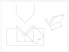
Since these days everyone is using CAD, so here i am going to share the basic blank calculation to enable students/freshers to make them reach close to exact value of the final product for CAD users, for instance see the below picture :
R/T = 1, then offset the inner radius by 33% of thk.
R/T = 5, then offset the inner radius by 50% of thk. i.e the Neutral axis is in center
For more precise calculations :
The above formula is basic, however, for practical working conditions i have developed the under-given formula, which is derived from the experimental data for to use in real/practical applications of sheet metal bending, for first time right results.Blank Length Calculation Formula (For Manual calculations) :
For users/technicians who are not cad literate, please follow the below formula :
Bend Radius = R1, R2, R3
Bend Angle = A1, A2, A3
Formula to calculate the Blank length = L + (R + K x T) x 𝛑A/180
For Example = (L1 + (R1 + K x T) x 𝛑A1/180) + (L2 + (R2 + K x T) x 𝛑A2/180) + (L3 + (R3 + K x T) x 𝛑A3/180) + L4
Let's calculate the Length up to R1, take R1=10 and T=5 and corresponding K= 0.4
Total Length = (25 + (10 + 0.4 x 5) x (3.14x115)/180)) ⇸ 49mm
Extracting the blank shape of complicated parts :
In year 2006, with the help of training on Unigraphics CAD software, i get familiar with the automatic process of blank calculation, which was never so easy and convenient. The Meta form command works by meshing the mid surface of the Cad model with one fixed surface and unfold the selected surface in magical form. With the extracted surface you only have to fine tune with K-factor.Nowadays it is called, One step calculation and here is the example : this advanced method is to use 3D cad (for complicated shapes) and FEA (One step form-ability analysis), as shown in the following pictures :


Sheet Metal part

Meshing of Part

Blank Shape
Method to be used in Siemens NX:
While using the Siemens NX software, the command ''Analyze formability - One step'' found under the more options. It is used to flatten the selected faces of the sheet metal using Finite element method and calculates the thinning, stress, strain and springback to predict the risk of forming.
Define the input in each step :
First step is to create the mid surface by using offset command and offset any face by half of the thickness.
1. Select the faces to unform : As the name suggest, you need to select the target face to unfold form the mid surface.
2. Target region : The target region is the area to kept as it is that means fixed area.
3. Boundary conditions : Select the boundary of the area to be unbent or unfold.
4. Material : The materials are already defined in the library, there are not much options to customize, so you have to choose one out of the given in the library.
5. Draw direction : Select the draw direction, means the same direction in which you are going to place or load in the bending or forming die during the process.
6. Thickness : Define the thickness of the part.
7. Calculation : in the calculation, select the mesh size and mesh the model, the tick button will check the quality of the mesh. Since there are not good options to edit the mesh quality, thereby you have to leave it as it is. Next button is to compute the results.
8. Result : In the result section, you can view stress, strain and unfolded blank along with sprinback calculation. The springback calculation is however not very reliable, only flattened surface is the major advantage. It is much like a automatic calculation with minor editing required during final die trials.
Method to be used in Altair Hyperform (one step)
About the Hyperworks - Hyperform
First of all you should be well versed with a Altair Hyperworks software and its manufacturing module called Hyperform. Inside Hyperform, select the one step option, it is being used for initial feasibility study with the feature of forming limit diagram for the prediction of thinning, thickening, wrinkle, cracks etc. Also it has the capability to unform the geometry and to generate the best possible layout and blank nesting with material saving reports.
Why correct blank size calculation plays important role :
The extracted blank shape is tentatively 80% correct, since it's from mid surface (Neutral Axis) and bend allowance has to take care at the Radius according to the calculation mentioned in the above table and blank shape to be scaled accordingly.Why correct Process design is mandatory for Final result :
Furthermore all holes to be pierced only after bending process by considering the positional accuracy, Since holes in blank may get deform/Oblong after bending and hole position may shift from the desired location, which should be therefore to be done after bending. The blank location in the bending die has a key role in maintaining the final dimensions.If you want to learn the Metal forming simulation, read the book "Practical guide to forming simulation"

The book is available via. the following links.
Or
Buy from here at 20% discount.
Or
Or
Buy the book from Notion press
Or
Or
Or
Or
Or
SOME MORE HELPFUL TOPICS :
Bending Force Calculation
Forming Limit Diagram
Sheet Metal blank size calculation
Lean Manufacturing Terminologies
Brief Comparison of Hydraulic and Mechanical press
TECHNICAL TERMINOLOGY OF WHEEL TIRE
Raw material calculation of Complex Deep drawn Geometry
Modify the product to make it aesthetically better and more cost effective
How creativity results in major cost savings
How concrete analysis resolve warranty issues
Proud of being Granted with your first patent
How hastened decisions affect the business in the long term
How cost reduction is the key factor to capture the market share
How to choose number of Draw process for deep drawn geometry
Essential parts of a draw die
Everything about patent
sheet metal processing and latest trends
Electric vehicle (EV) – Future of Transport


)
0 Comments