Correctly define the problem
We were
informed about the severe cracks in the parts reported by leading agricultural
OEM in India and team has to report back as soon as the issue escalate further.
Warranty hazards in a structural members are very severe due to their life
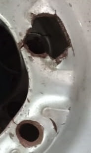
threatening nature. Up on investigating, there were the signs of severe damage,
such as an accidental situation. Service teams are creating panic situations; however,
engineers should stay calm before reaching to any conclusion in hastened way.
Failed part
Try to figure out the source of problem
There might
be the several reasons, such as improper usage, accidental condition, applying
excessive torque to tighten, sudden deflation of air resulting in imbalance of
vehicle.
Physical
presence at the site of application is highly appreciated to understanding the
loading conditions and usage patterns.
Conditions under which your part failed
After you
reach at the site and the usage patterns are vivid to you, try to access the
capture the maximum information in the form of pictures, videos, notes. Since
this is your running part, being supplied throughout the years. The sudden
failures are the result of change, here ‘’change’’ is the key thing which you
have to co-relate. Whether it is the new area where vehicle was never sold or
tested or the evolution of new application or change in application or change
in mating part or change in vehicle model, where your part was never tested.
Check with the mating part
Here in my
part there are the three possibilities: Change in tire size or change in axle
hub design or change in vehicle model.
Up on
conclusion it was found that the customer has changed the Hub-axle design as
VA-VE initiative without intimation to the supplier, whose part is being
suffered from severe failures.
Mating part
Any change in mating part would adversely
affect the function of your part
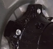
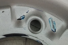
The hub design has been changed to the extent that should have not been there, New engineers take initiatives of VA-VE in the greed of appreciation in terms of money and their idea eventually get approved by their in-experienced managers without understanding the severity of the function. Which therefore imparting pressure to modify the mating part, that otherwise makes no sense.
Old Hub Design New Hub Design
Use of bench marking techniques
By blue
matching with the mating part, the problem becomes more vivid, as the
definition of pressure works here (force acting on per unit area). The contact area here is negligible and pressure/load is same as in the case of old mating part, causing the more stress concentration and weakening of the area.
Arresting the problem
Brainstorming to find out the final solution
Take the help of engineering techniques / Finite element analysis
Solid foundation of your analysis is the key to success / Not plan A or B
If you want to learn the Metal forming simulation, read the book "Practical guide to forming simulation"
The book is available via. the following links.
Or
Buy from here at 20% discount.
Or
Or
Buy the book from Notion press
Or
Or
Or
Or
Or
SOME MORE HELPFUL TOPICS :
Bending Force Calculation
Forming Limit Diagram
Sheet Metal blank size calculation
Lean Manufacturing Terminologies
Brief Comparison of Hydraulic and Mechanical press
TECHNICAL TERMINOLOGY OF WHEEL TIRE
Raw material calculation of Complex Deep drawn Geometry
Modify the product to make it aesthetically better and more cost effective
How creativity results in major cost savings
How concrete analysis resolve warranty issues
Proud of being Granted with your first patent
How hastened decisions affect the business in the long term
How cost reduction is the key factor to capture the market share
How to choose number of Draw process for deep drawn geometry
Essential parts of a draw die
Everything about patent
sheet metal processing and latest trends
Electric vehicle (EV) – Future of Transport


0 Comments