Check for Draw to Height ratio
The D/H ratio is the basic ratio to have a look at the feasibility to perform a round / cylindrical draw process in a one or more than one process.
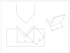
REFERENCE DEEP DRAWN PART
D = Outer dia. of the shell (15 inch, as shown in the sketch)
H = Height of the cylinder (20 inch, as shown in the sketch)
If D/H should be equal to or more than 1, there is a possibility to do it in a single draw.
In case, it is less than 1, then you have to go for a 2 or more draw operations.
For multiple draw process
In case D/H ratio is less than 1, then what is next. It is evident that it's more than one, but how much ?
The answer is complicated, there is no thumb rule, however based on my experience and compilation of years of experimental data, the following rules has been established.
For 1st draw, there should be the 60-70% reduction in diameter.
For 2nd draw, there should be the 40-45% reduction in diameter.
For 3rd draw, there should be the 20-25% reduction in diameter.
The base / original diameter with respect to whom, the reduction is applicable, that is the blank diameter.
Calculate the blank diameter
To calculate the blank dia. of the cylindrical part, the volume method to be used.
Volume of a cylinder is = ¶r²h
The volume of a blank, is also calculated by the same formula.
Volume of cylinder = volume of the calculated blank size
Let's say, the volume of cylinder is 108.6640 cubic inch.
Now for blank :
D = to be calculated
Thickness = 0.1 inch (same as thickness of the part)
108.6640 = 3.14 x R x R x 0.1
R = 18.6 and D = 37.2 inch
Decide the No. of Draw
Fore multiple draw process, there formula is same as mentioned earlier.
For First draw, the Final dia. of the part after draw is = (37.2 x 65%) = 24.18 inch
For Second draw, the possible reduction is = (24.18 x 40%) = 9.7 inch
Since our Target diameter is 15 inch, that means it's possible to draw the part in 2 draw stages.
Limitation of this basic method
This is a basic method, highly successful in the calculation of cylindrical deep drawn geometry.
Sometimes, other shapes such as square, pentagon and hexagon can be calculated. However, their blank size calculation is quite hard, since this is a volume based calculation best suited for round parts.
Defects of the metal forming process
The most painful and most frequent defects are wrinkles, thinning, springback and splits or cracks. Few methods are being used around the industry to cope with the main defects, based on the experience of the technicians. However, the correct process is the most vital, since it involves the correct geometry followed by number of steps to reach at final geometry. Which demands for specific experience or higher number of iterations, Nowadays the simulation software's comes under CAE (computer aided engineering), used the finite element analysis to predict the common defects in design stage, prior to die manufacturing.
Wrinkles : Wrinkling in a draw are series of ridges form radially in the drawn wall due to compressive buckling. Practically these are duo to low blank holder pressure due to which material slips and wrinkles formed. The optimum blank holding pressure is the key, however in certain cases it doesn't work. Then draw beads are the solutions, the location and shape of draw bead is the challenge, which can be analysed with FEA during design stage prior to tool manufacturing.
Cracks : Crack in the vertical wall due to high tensile stresses, some small radius block the material flow and results in excessive thinning at that point usually more than 40% of the sheet thk. result in cracks. In some cases it may happen due to excessive blank holder pressure, which restrict the metal flow. Somewhere it might be due to wrong process design, like try to make a more deep draws in a single stage, which otherwise feasible only in two stages.
Thinning : Excessive Stretching in the vertical wall due to high tensile stresses cause thickness reduction specifically on the small radius in the metal parts. The image highlights the thinning portions, however up to 20% thinning is allowed due to process limitations.
How FEA Helps : Nowadays FEA software's such as LS DYNA, AUTOFORM, HYPERFORM, PAMSTAMP are very good for virtual process simulations prior to product manufacturing. The defects such as Wrinkles, thinning and cracks can be seen in the design stage right just before the process design, results in correct process selection and reduction in lead time and save valuable money, which otherwise invested in hectic manufacturing iterations.


0 Comments